Pick the wrong temperature sensor and you’ll spend the next five years chasing drift, nuisance trips, and calibration headaches nobody budgeted for. That’s the real cost of getting the RTD vs thermocouple temperature transmitter decision wrong — not the sensor price tag, but the maintenance calls that follow it. Plant engineers wrestle with this choice constantly, usually under pressure from a project deadline that doesn’t leave room for second-guessing.
Here’s the short version: RTDs win on accuracy and stability in moderate temperature ranges, while thermocouples win on ruggedness and extreme heat tolerance. But that one-line answer hides a lot of nuance that matters once you’re staring at a P&ID and a vendor catalog.
This guide breaks down how each sensor works, where each temperature transmitter type actually earns its keep, and how to match your choice to the process conditions you’re dealing with — not the conditions in a textbook.
RTD vs Thermocouple Temperature Transmitter: The Quick Answer
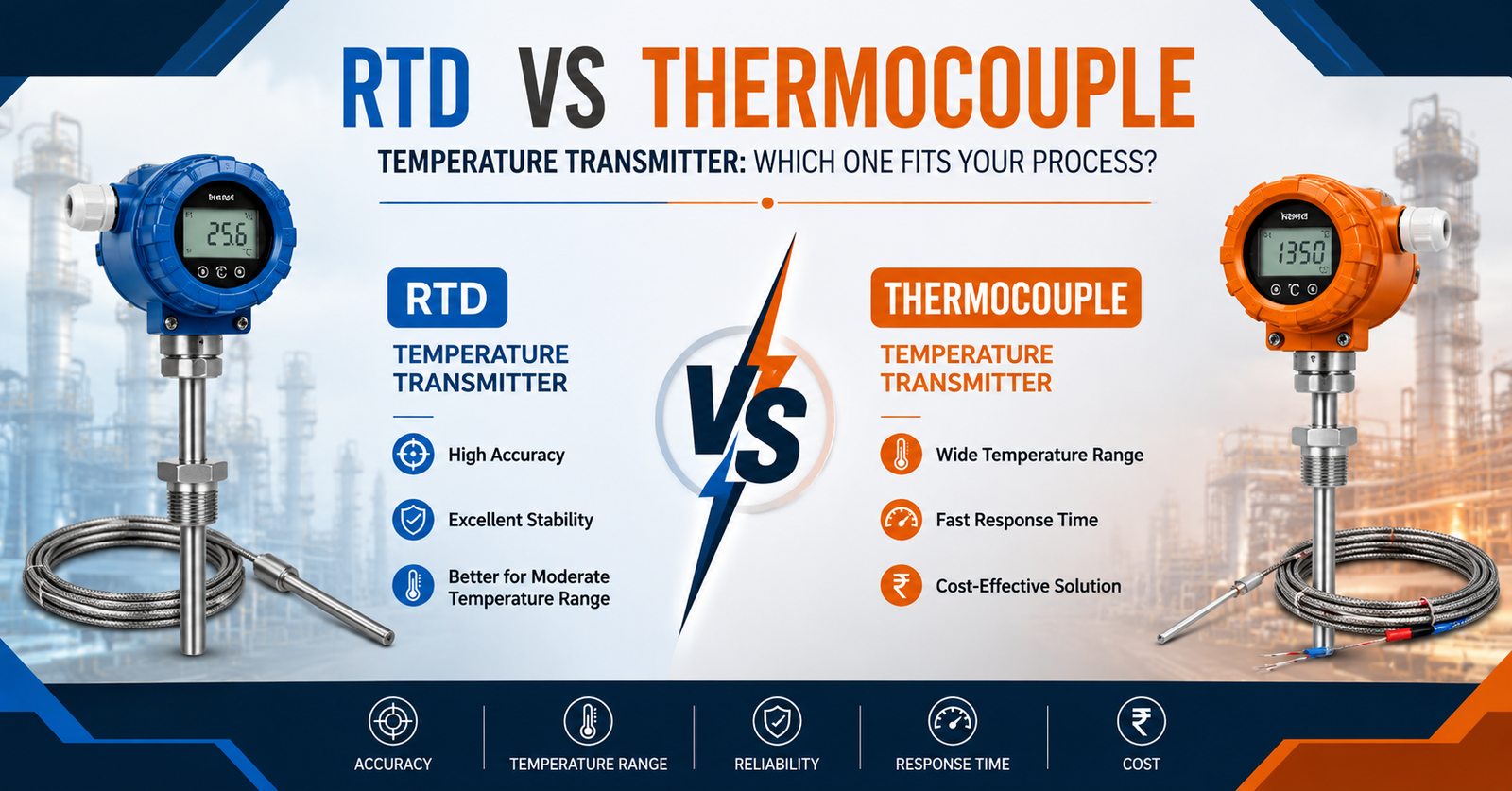
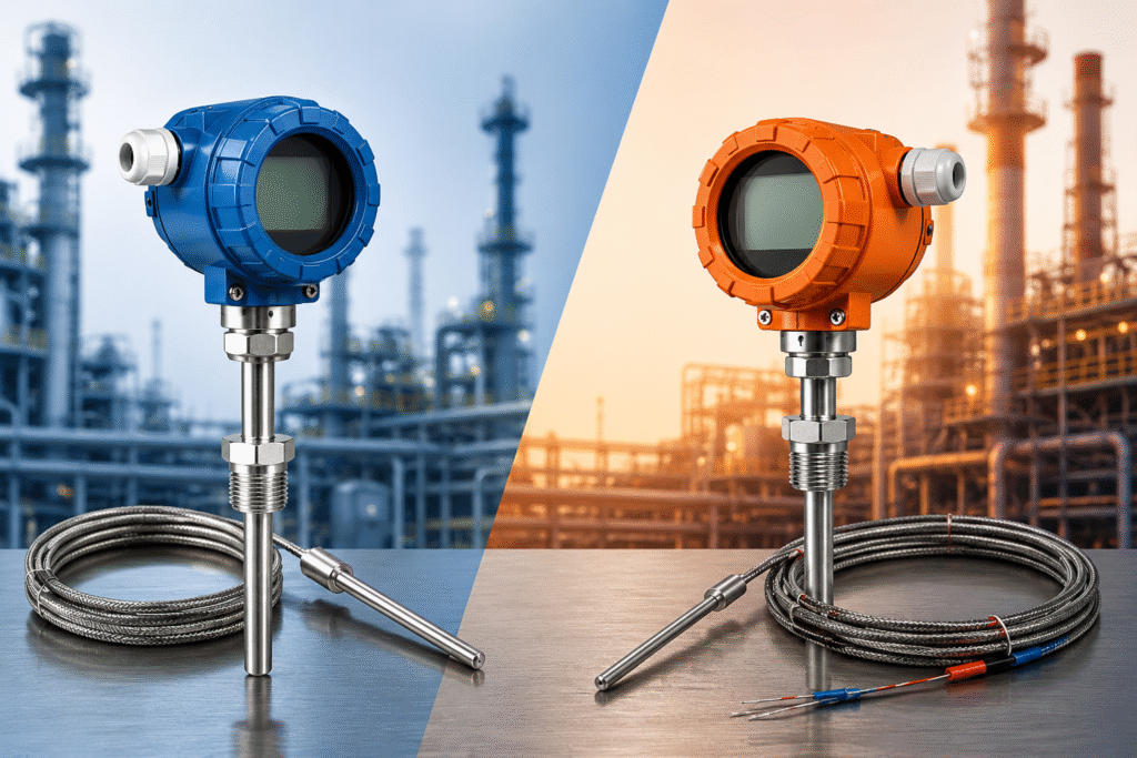
An RTD-based temperature transmitter uses a resistance temperature detector — typically platinum — that changes electrical resistance predictably as temperature changes, giving you high accuracy and repeatability from roughly -200°C to 850°C. A thermocouple-based transmitter uses two dissimilar metal wires joined at a junction that generates a small voltage proportional to temperature, and it can survive far higher temperatures, up to 1800°C in some types, though with less precision.
If your process runs below 600°C and accuracy matters more than ruggedness, go RTD. If you’re measuring furnace exhaust, kiln temperatures, or anything pushing past 850°C, a thermocouple is often your only practical option.
That’s the headline. Now let’s get into why.
What Makes RTD and Thermocouple Sensors Different
The two technologies solve the same problem — converting heat into a readable electrical signal — through completely different physics. That difference shapes everything downstream: wiring, transmitter configuration, drift behavior, and even how you’ll troubleshoot a bad reading five years from now.
How RTDs Work
A platinum RTD sensor (often called Pt100 or Pt1000, referring to its resistance in ohms at 0°C) relies on a simple fact: metal resistance rises in a near-linear, well-documented curve as temperature climbs. Feed it a small measuring current, read the resistance, and you get a temperature value that’s accurate to within a fraction of a degree.
Three things define RTD performance in the field:
- Wiring configuration — 2-wire setups are cheap but introduce lead-wire resistance error; 3-wire and 4-wire configurations cancel that error out, and 4-wire is the gold standard for lab-grade accuracy.
- Element construction — wire-wound elements are more accurate but more fragile; thin-film elements are cheaper and more vibration-resistant, which matters on rotating equipment.
- Self-heating error — the measuring current itself generates a tiny bit of heat, which can skew low-temperature readings if the excitation current isn’t kept low.
How Thermocouples Work
A thermocouple exploits the Seebeck effect: join two different metals at one end, and a temperature difference between that junction and the “cold” reference end produces a measurable millivolt signal. Different metal pairings — Type K (chromel-alumel), Type J (iron-constantan), Type N, Type R, Type S — cover different temperature bands and chemical environments.
Type K is the workhorse of general industrial use, rated to roughly 1260°C and tolerant of oxidizing atmospheres. Type R and Type S, using platinum-rhodium alloys, handle temperatures near 1600–1700°C and show up in glass manufacturing, cement kilns, and high-end lab furnaces.
The catch: thermocouple signals are tiny (microvolts per degree) and nonlinear, which means the transmitter has to do real work — cold-junction compensation and linearization — to turn that raw voltage into a trustworthy reading.
Temperature Transmitter Types: Where RTD and Thermocouple Fit In
Not every temperature transmitter is built the same way, and matching transmitter type to sensor type isn’t optional — it’s the difference between a working loop and a nuisance alarm. Broadly, you’re choosing across three transmitter configurations.
- Head-mounted transmitters — sit directly in the sensor’s connection head, minimizing wiring runs and EMI pickup. Common on both RTD and thermocouple installations where the sensor is field-mounted.
- DIN-rail (rack-mounted) transmitters — installed in a control panel or junction box, useful when you’re consolidating multiple signals or need easier access for calibration.
- Flanged temperature transmitter assemblies — combine the sensor, thermowell, and transmitter into one flanged unit that bolts directly onto a vessel or pipe, common in refining, chemical processing, and anywhere a threaded connection isn’t rated for the pressure class.
A flanged temperature transmitter setup matters more than people expect on high-pressure lines. Get the flange rating or thermowell wake-frequency calculation wrong, and you’re looking at sensor fatigue failure — a genuinely unpleasant thing to discover during a shutdown inspection.
Accuracy, Range, and Response Time Compared
Numbers settle arguments faster than opinions do, so here’s how the two stack up on the metrics that actually drive a purchasing decision.
Parameter | RTD Temperature Sensor | Thermocouple Temperature Sensor |
Typical accuracy | ±0.1°C to ±0.3°C | ±1°C to ±2.2°C (Type K) |
Temperature range | -200°C to 850°C | -270°C to 1800°C (type-dependent) |
Response time | Slower (1–5 sec typical) | Faster (0.5–2 sec, thin-junction) |
Signal output | Resistance (needs excitation) | Voltage (self-generated, small) |
Long-term drift | Very low | Moderate, increases with cycling |
Vibration tolerance | Lower (wire-wound types) | Higher |
Relative cost | Higher sensor cost | Lower sensor cost |
Accuracy is where RTDs pull ahead decisively — a Class A Pt100 can hold ±0.15°C, which is difficult for any thermocouple to match without expensive calibration and frequent replacement. But thermocouples respond faster to temperature swings, which matters in fast thermal processes like extrusion or reactor start-up sequences where lag time translates directly into product loss.
Response time isn’t purely academic, either. On a process with rapid thermal cycling, a slow RTD response can mean your control loop is always chasing a temperature that already changed. That’s a legitimate reason engineers sometimes accept the accuracy trade-off and go with a thermocouple anyway.
Choosing Between RTD and Thermocouple Temperature Transmitters for Your Process
There’s no universal winner here — only a better fit for your specific conditions. Ask these questions before you specify anything.
What’s your actual temperature range, including upset conditions? Don’t just size for normal operation. If a runaway condition could push a reactor past 900°C even briefly, an RTD won’t survive it, full stop.
How much does accuracy actually matter to your process economics? In custody transfer, pharmaceutical batch control, or any application tied to product quality specs, the tighter tolerance of an RTD temperature sensor often pays for itself within a year through reduced rework and tighter quality bands.
What’s the vibration and mechanical stress profile? Compressor discharge lines, near rotating equipment, or anywhere shock loading is common — thermocouples generally hold up better mechanically, particularly grounded-junction types.
What’s your budget across the sensor’s full lifecycle, not just purchase price? RTDs cost more upfront but drift less, meaning fewer recalibration cycles. Thermocouples are cheap to replace but need more frequent verification, especially past 500°C where junction degradation accelerates.
A rough rule plant engineers use: RTD for anything under 600°C where accuracy and stability matter, thermocouple for anything hotter or where mechanical abuse is a given.
HART Temperature Transmitter and Smart Configuration Considerations
Most modern installations, whether RTD or thermocouple, run on a HART temperature transmitter platform rather than a basic analog 4-20mA unit — and the difference matters more than the spec sheet suggests. HART protocol layers digital communication onto the existing analog signal, which means you can pull diagnostics, re-range, and reconfigure the transmitter remotely without pulling it out of the field.
That’s a genuinely practical advantage during commissioning. Instead of climbing a platform to swap a jumper for a different sensor type, a HART-capable smart transmitter often lets you reconfigure input type, range, and alarm limits from a handheld communicator or asset management software at the control room level.
HART transmitters also support features that matter for reliability programs:
- Sensor drift alerts before the reading goes fully out of spec
- Dual-sensor input with automatic failover or averaging
- Sensor break detection that fails to a known safe state rather than a frozen last-value
For safety instrumented systems, this diagnostic depth isn’t a luxury — it’s often a requirement under IEC 61508 / IEC 61511 for achieving the required Safety Integrity Level.
Industrial Temperature Monitoring: Real-World Application Tips
Theory aside, here’s what tends to trip people up once the transmitter is actually in the field.
- Match the thermowell material to the process fluid, not just the sensor. A perfectly good RTD will still read wrong or fail early if the thermowell corrodes in a chloride-rich stream.
- Check cold-junction compensation on thermocouple installs. A transmitter with a faulty or poorly located CJC circuit introduces an offset error that’s maddening to diagnose because it looks like sensor drift.
- Don’t undersize the insertion length. Both RTDs and thermocouples need adequate immersion depth — too shallow, and you’re measuring the pipe wall temperature, not the process fluid.
- Verify loop resistance on long RTD wire runs. A 4-wire configuration solves lead resistance error, but only if it’s actually wired correctly at both ends; a mis-wired 4-wire RTD behaves worse than a properly wired 3-wire one.
- Budget for periodic verification, not just initial calibration. NIST-traceable calibration standards, referenced by organizations like NIST itself, are worth consulting when setting your recalibration interval for critical loops.
Getting industrial temperature monitoring right is rarely about picking the fanciest transmitter on the shelf. It’s about matching sensor physics, transmitter configuration, and mechanical installation to what your process actually does — including on its worst day, not just its average one.
Conclusion
The RTD vs thermocouple temperature transmitter decision comes down to two questions: how hot does your process actually get, and how much does a tenth of a degree matter to your bottom line? RTDs deliver tighter accuracy and lower drift for processes under 600°C; thermocouples take the abuse of extreme heat and rough mechanical conditions that would destroy an RTD element.
Don’t let a vendor default steer this decision — pull your actual process data, check your upset-condition temperature ceiling, and size the sensor and transmitter around that, not around what’s already sitting in the storeroom. If you’re mid-way through specifying a new installation and want a second opinion on sensor selection or transmitter configuration, [Link to related post] walks through a full instrumentation checklist worth reviewing before you finalize the purchase order.
FAQ
What is the main difference between an RTD and a thermocouple based temperature transmitter?
An RTD transmitter measures temperature through changes in electrical resistance in a platinum element, offering higher accuracy and stability. A thermocouple transmitter measures a small voltage generated at a junction of two dissimilar metals, offering a wider temperature range and better tolerance for harsh, high-heat environments.
Which is more accurate, RTD or thermocouple?
RTDs are more accurate, typically holding ±0.1°C to ±0.3°C compared to a thermocouple’s ±1°C to ±2.2°C. This makes RTDs the preferred choice for processes where tight temperature control directly affects product quality.
Can I use a thermocouple in industries requiring very high temperature measurement?
Yes, thermocouples are specifically suited for very high temperature measurement, with certain types rated up to 1800°C. Industries like glass manufacturing, cement production, and metal smelting rely on thermocouples precisely because RTDs can’t survive those temperatures.
Does a temperature transmitter need to match a specific sensor type?
Yes, a temperature transmitter must be configured for the exact sensor type it’s paired with — RTD transmitters and thermocouple transmitters use different input circuitry and linearization tables. Using a mismatched configuration produces inaccurate readings even if the wiring looks correct.
What is a smart temperature transmitter and how is it different?
A smart temperature transmitter uses digital protocols like HART to allow remote configuration, diagnostics, and range adjustment without physically accessing the device. Unlike basic analog transmitters, smart units can flag sensor drift, support dual-sensor failover, and integrate with asset management systems for predictive maintenance.