
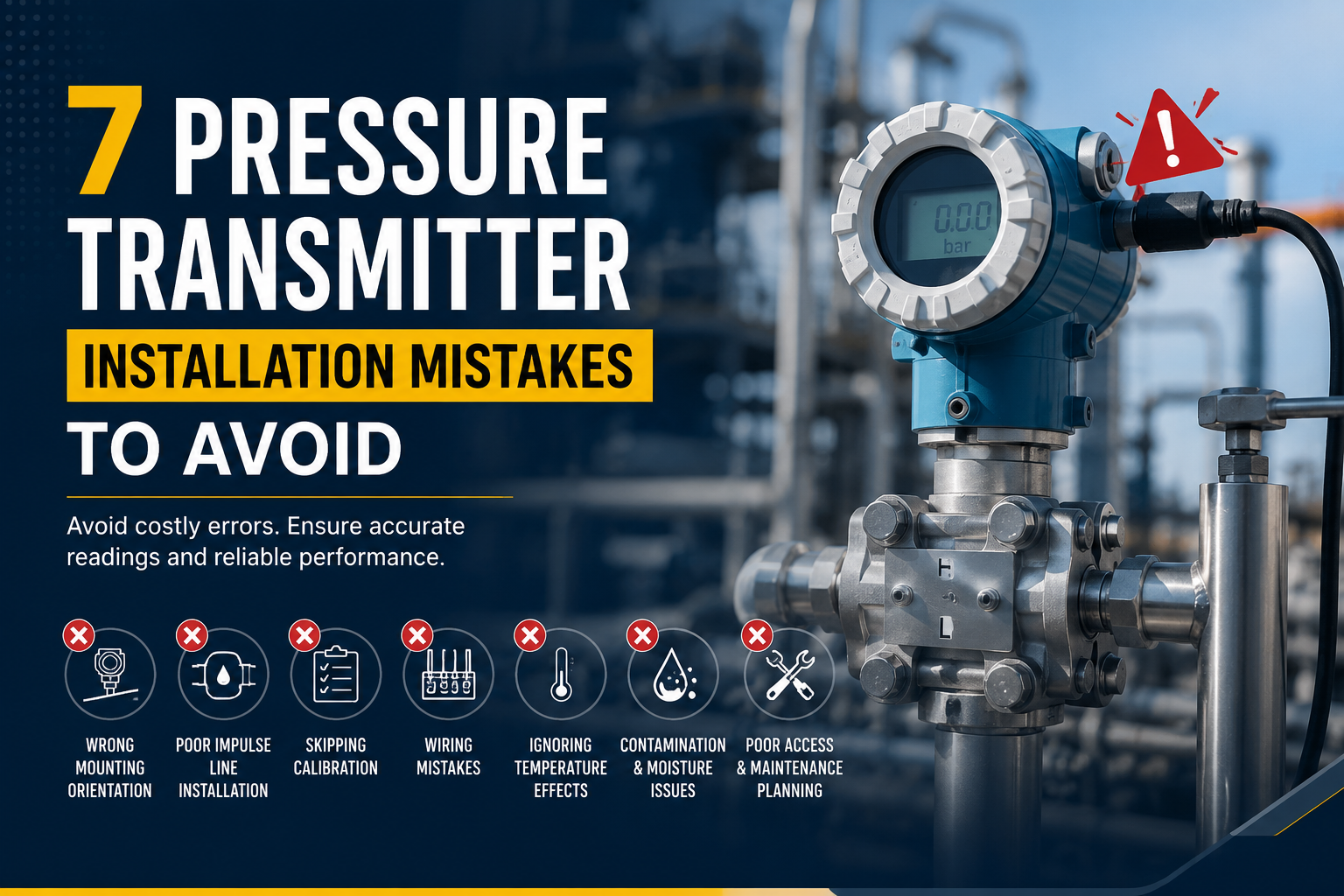
Introduction
Here’s the uncomfortable truth: most pressure transmitter problems have nothing to do with the transmitter itself. They start at installation. A perfectly good instrument, rated and calibrated to spec, can still throw wrong readings, drift within weeks, or fail outright — all because of how it was mounted, wired, or connected to the process.
Pressure transmitter installation mistakes are more common than most plant teams like to admit, and they’re expensive. A misread pressure loop can trigger false trips, mask a real upset, or quietly corrode a diaphragm over months until the transmitter fails during a shutdown you can’t afford. In this guide, you’ll learn the seven mistakes technicians and engineers make most often, why each one hurts accuracy or reliability, and exactly how to avoid them on your next installation.
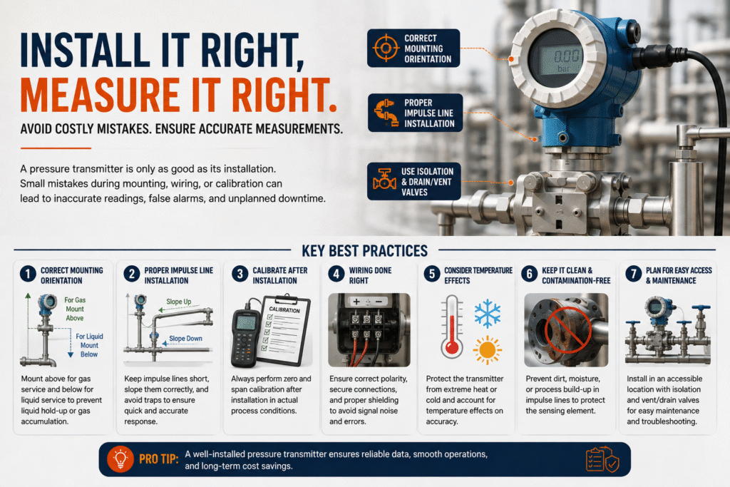
Mistake #1: Getting the Mounting Orientation Wrong
Transmitter mounting orientation isn’t a minor detail — it directly affects your zero reading. Mount the instrument even a few degrees off from what the calibration assumed, and you introduce a static offset that no amount of process tuning will fix.
Think about what’s actually happening inside the transmitter. The sensing diaphragm reacts to the weight of the fluid column sitting above it, along with the process pressure itself. Change the orientation, and you change how gravity pulls on that fluid column relative to the sensor. On a liquid service, that offset might be small. On a low-range application, it can be the difference between a usable signal and noise.
Practical fixes:
- For liquid service, mount the transmitter below the tapping point so trapped gas can rise back into the process line instead of sitting against the diaphragm.
- For gas service, mount it above the tapping point so any condensate drains back rather than pooling in the impulse line.
- For steam service, always fill the impulse line with condensate before final zero adjustment — steam transmitters are notoriously sensitive to this.
- Re-zero the transmitter after installation, in its final mounted position, not on the bench.
A five-minute orientation check before you tighten the mounting bracket saves a recalibration trip later.
Mistake #2: Poor Impulse Line Installation
If there’s one area where installation errors snowball into chronic accuracy problems, it’s the impulse line. Impulse line installation looks simple on a P&ID — just tubing from tap to transmitter — but the routing details matter more than most people expect.
Trapped air pockets in a liquid line, or trapped liquid in a gas line, both distort the pressure signal your transmitter actually sees. Add a long, poorly sloped run, and you also introduce lag — your transmitter starts reporting where the process was, not where it is now.
Common impulse line errors:
- Horizontal runs with no slope, which let gas bubbles or condensate sit in the line indefinitely.
- Excessive line length, which slows dynamic response and can cause the loop to hunt during fast transients.
- Undersized tubing that clogs easily in dirty or viscous service.
- Missing isolation and drain/vent valves, which makes routine maintenance a headache and often leads technicians to skip it.
As a rule of thumb, slope impulse lines at least 1 inch per foot, keep runs as short as practical, and always install a five-valve or three-valve manifold so you can isolate, equalize, and vent the transmitter without shutting down the process. This single habit will save you more troubleshooting hours than almost anything else on this list.
Mistake #3: Skipping or Rushing Calibration After Installation
Here’s something a lot of teams get backwards: they calibrate the transmitter on the bench, then assume that calibration holds once it’s mounted in the field. It doesn’t — not exactly. Mounting position, impulse line fill, ambient temperature, and even cable length can shift the actual zero and span you get in service.
Transmitter calibration errors introduced at this stage are sneaky because the loop often looks fine at startup. The real symptom shows up weeks later as slow drift, or as a control loop that’s technically “working” but running a few percent off from where the process actually sits.
What proper post-installation calibration should cover:
- A field zero check with the transmitter in its final mounted position and impulse lines filled.
- A verification of span against a certified reference standard — not just the transmitter’s own display.
- Documentation of ambient temperature at the time of calibration, since many smart transmitters compensate for temperature but not perfectly.
- A five-point linearity check for critical loops, rather than a simple two-point zero/span adjustment.
If you’re managing multiple loops during a unit turnaround, it’s tempting to batch calibration and rush it. Resist that. A ten-minute shortcut here often turns into a half-day troubleshooting exercise three weeks into the next production run.
Mistake #4: Wiring and Grounding Errors
Can incorrect wiring damage a pressure transmitter? Yes, and more often than technicians expect. Reversed polarity on a loop-powered 4–20 mA transmitter usually won’t destroy the unit — most modern designs have reverse-polarity protection — but miswiring into the wrong terminals, applying line voltage by mistake, or grounding the signal loop at more than one point absolutely can.
Multiple ground points are the quiet killer here. They create ground loops, which show up as noisy, unstable readings that are maddening to diagnose because the transmitter itself tests fine on the bench every time. The fault is in the wiring path, not the instrument.
Wiring practices worth enforcing on every job:
- Ground the signal loop at one point only — typically at the control system end, not at the transmitter.
- Use shielded, twisted-pair cable for the 4–20 mA loop, and terminate the shield correctly per the manufacturer’s wiring diagram.
- Keep instrument signal cable separated from power cabling in the cable tray; route them in different trays or conduits where possible.
- Torque terminal screws to spec — a loose connection under vibration is a classic cause of intermittent signal loss that looks like a “ghost” instrument fault.
- Double-check supply voltage against the transmitter’s rated range before energizing the loop for the first time.
A quick continuity and insulation resistance check before commissioning catches most of these problems before they become a shutdown call at 2 a.m.
Mistake #5: Ignoring Over-Pressure Protection
Why is this on almost every troubleshooting list from instrumentation vendors? Because over-pressure events during installation, hydrotesting, or line flushing are one of the most common ways a perfectly good transmitter gets permanently damaged before it ever measures a real process value.
Most transmitters have an over-pressure rating well above their normal operating range, but hydrotest pressures and unexpected surges during commissioning can exceed even that limit. Once the diaphragm is stretched past its elastic range, you’re looking at a shifted zero at best and a ruptured sensor at worst.
How to prevent over-pressure damage:
- Isolate the transmitter using the manifold block valve before hydrotesting or line flushing, and don’t reconnect it until test pressures have been released.
- Check the transmitter’s rated proof pressure against the maximum expected test pressure before the test plan is finalized, not the day of.
- Open and close manifold valves slowly. Slamming a block valve open against a static-filled transmitter creates a pressure spike that a slow, gradual opening avoids entirely.
- For known high-transient services, specify a transmitter with built-in over-range protection or add a snubber to dampen pressure spikes.
This is one of those mistakes that costs almost nothing to prevent and a full instrument replacement to fix after the fact.
Mistake #6: Overlooking Environmental and Vibration Factors
Process instrumentation best practices don’t stop at the impulse line and the wiring terminal — the surrounding environment matters just as much. Transmitters mounted near rotating equipment, compressors, or high-vibration piping can suffer accelerated wear on internal components and, over time, fatigue cracking in the process connection.
Extreme ambient temperature is another overlooked factor. A transmitter rated for a wide operating range will still show more drift at the edges of that range than in the middle of it, and direct sun exposure on an outdoor installation can push internal temperatures well above what the datasheet implies.
Simple mitigation steps:
- Use flexible capillary connections or remote seals in high-vibration areas instead of hard-piping the transmitter directly to a vibrating line.
- Install a sunshade for outdoor transmitters in hot climates — it’s inexpensive and meaningfully reduces thermal drift.
- Keep transmitters away from steam lines, exhaust stacks, or other radiant heat sources whenever the layout allows it.
- For high-vibration services, check manufacturer specifications for vibration-rated models rather than assuming a standard unit will hold up.
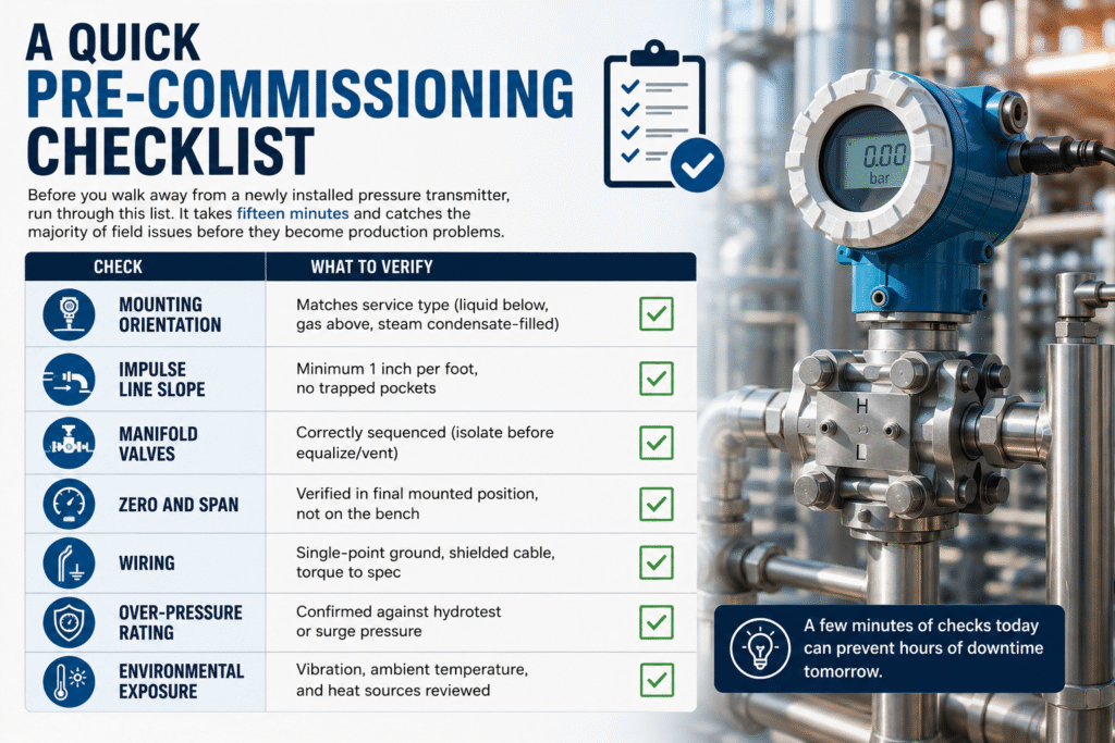
A Quick Pre-Commissioning Checklist
Before you walk away from a newly installed pressure transmitter, run through this list. It takes fifteen minutes and catches the majority of field issues before they become production problems.
Check | What to Verify |
|---|---|
Mounting orientation | Matches service type (liquid below, gas above, steam condensate-filled) |
Impulse line slope | Minimum 1 inch per foot, no trapped pockets |
Manifold valves | Correctly sequenced (isolate before equalize/vent) |
Zero and span | Verified in final mounted position, not on the bench |
Wiring | Single-point ground, shielded cable, torque to spec |
Over-pressure rating | Confirmed against hydrotest or surge pressure |
Environmental exposure | Vibration, ambient temperature, and heat sources reviewed |
Getting It Right the First Time
Pressure transmitter installation mistakes rarely announce themselves immediately. That’s what makes them dangerous — a wrong orientation, an unsloped impulse line, or a shared ground point can sit quietly in your loop for weeks before it shows up as a nuisance trip, a drifting reading, or a failed instrument during the worst possible shift. Treat installation with the same rigor you’d give calibration, because in practice, the two are inseparable.
If you’re specifying transmitters for a new project or troubleshooting a loop that’s never behaved quite right, walk through the checklist above before you assume the instrument itself is at fault. Nine times out of ten, the fix is in the installation, not the transmitter. For deeper guidance on selecting the right sensing technology for your process, the Instrument Society of America (ISA) publishes detailed standards on pressure measurement installation practices worth keeping on hand.
FAQ
What is the most common mistake when installing a pressure transmitter?
Incorrect mounting orientation relative to the process service is the single most common mistake. It shifts the zero reading and often goes unnoticed until the loop drifts or fails a calibration check weeks later.
How does improper impulse line installation affect accuracy?
Poorly sloped or oversized impulse lines trap air in liquid service or condensate in gas service, which distorts the actual pressure signal reaching the transmitter. This shows up as inaccurate readings, slow response, or an unstable loop during process transients.
Can incorrect wiring damage a pressure transmitter?
Yes. While most transmitters tolerate reversed polarity, applying incorrect voltage, miswiring terminals, or creating multiple ground points can damage the unit or cause persistent signal noise. Always verify wiring against the manufacturer’s diagram before energizing the loop.
Why is calibration important after installation?
Bench calibration doesn’t account for the transmitter’s final mounted position, impulse line fill, or field ambient conditions, all of which shift the actual zero and span. Field calibration after installation confirms the transmitter reads accurately under real operating conditions.
How can I prevent damage from over-pressure during installation or testing?
Isolate the transmitter with its manifold block valve before hydrotesting or line flushing, and confirm the test pressure won’t exceed the transmitter’s rated proof pressure. Open manifold valves slowly to avoid pressure spikes hitting the diaphragm.